HIL Simulation
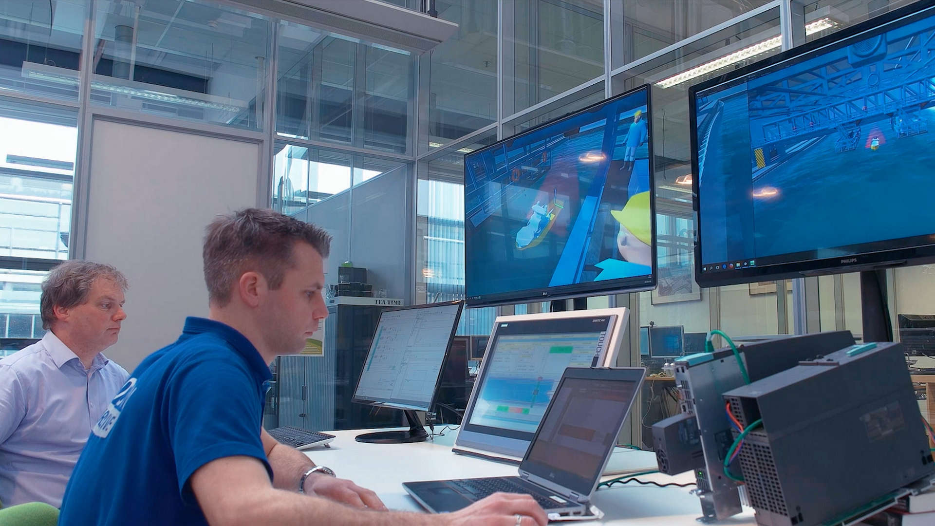
Our digital twins are simulation models that mimic real machines. We apply physics and use measurement data from other machines to make our simulation models behave exactly as the real machine. And we are experts in letting these models run in real-time. This allows us to couple our digital twins to external control software. This is called Hardware-in-the-Loop (HIL) simulation.
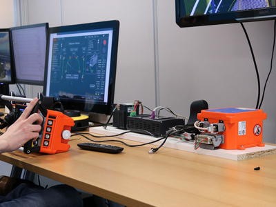
With HIL simulation only the physical part of a digital twin is used. The inputs (actuator setpoints) and outputs (sensor data) are coupled to a PLC running the control software. This allows you to test the control software without the need of a real machine.
What is HIL testing?
Hardware-in-the-Loop (HIL) simulation is a technique that is used for testing control systems. Carrying out a HIL simulation to test a control system is called HIL testing.
The machine or physical part of the system (which we call the plant) is normally connected with the control system, through actuators and sensors. With HIL testing the plant is replaced by a simulation of the plant (which we call the HIL simulator). If the HIL simulator is designed well, it will accurately mimic the plant, and can be used to test the control system. Some HIL simulators are equipped with 3D visualization and represent the plant so well that they can be used for training. These HIL simulators are called training simulators.
PLCs for HIL Simulation
Windows is a not a real-time operating system. With special care it can be used for general purpose HIL simulators. In some cases this is not good enough:
- The control system runs at high speeds ( > 100 Hz).
- The plant model only runs well at high simulation speeds.
- Too much jitter (time delay between control system and plantmodel) will make the system unstable.
Controllab can provide a HIL simulator based on a PC with Real-Time Linux, which allows communication with a fieldbus at high speeds (> 5 kHz) and has low jitter (< 0.1 ms).
The Bachmann M1 PLC supports the running of ANSI C-code. Users of this PLC have the option to run the plant model as C-code directly on the controller. The plant model can be connected with the control system by sharing SVI variables. This allows direct testing of the control system without additional hardware.
- Siemens S7
- Siemens S7-150
- Beckhoff
- Raspberry PI
Fieldbus Systems
Hard-Wired Connection; Modern machines have many actuators and are loaded with sensors. A control system will therefore have many connections with the machine to convert actuator setpoints and read sensor data. These connections will be mostly electrical wires transporting analog or digital information.
A pure HIL simulator will mimic the plant at the connection level and allow the wires to be switched from the plant IO to the HIL simulator IO. If the HIL simulation has been completed, you switch the wires to the plant and start the machine! There are however some drawbacks:
The wires transport information at very high frequencies (typically MHz). To mimic this, the HIL simulator has to run at ultra high speeds or use dedicated IO to generate these high frequencies. Many IO components are required to connect all the wires.
Most industrial controllers run at clock frequencies of 50 – 250 Hz. To easily connect IO components with the controller, a fieldbus is used. A fieldbus combines data and addresses to connect multiple IO points. A fieldbus carries information at the same speed as the clock frequency of the controller.
Most HIL simulators directly connect to the fieldbus of a controller. This will reduce the number of IO components to one fieldbus connector and reduce the required speed of the HIL simulator. Controllab can provide HIL simulators for many types of fieldbus systems.


